• chevron_right

      8-Channel relay controller with keypad and RS485 interface (2)

      pubsub.slavino.sk / onetransistor · Saturday, 10 December, 2022 - 16:15 edit · 1 minute

    In the previous post I built a front panel with 8 push buttons which will be used to activate a module of 8 relays. Having so many I/O lines I had to come with a solution to be able to read and set each one of them with common microcontrollers. I ended up using 74HC165 for inputs and 74HC595 for outputs. These ICs are shift registers controlled using a serial synchronous protocol similar to SPI.

    In this post you will see the entire outdoor unit. In the end there will be two units, the outdoor one with keypad and relays; the other is the indoor unit with Wi-Fi connectivity and MQTT capabilities. A keypad will be featured on this one too. I went with this approach because I want a robust implementation without Wi-Fi dependency. Nevertheless the keypad on outdoor unit can be remotely disabled to prevent unauthorized use. I decided to use two units after a failed design which implied the use of an ESP8266 board directly as the MCU of outdoor unit. I had problems with voltage levels (shift registers are both 3.3 V and 5 V compatible, however my relay board is 5 V only, while ESP8266 is 3.3 V only; besides that, 3.3 V applied to shift registers powered from 5 V is not recognized as digital HIGH).

    Relay controller inside plastic box
    Relay controller inside plastic box

    Read more

    Značky: #Elektro, #RS485, #PCB, #74HC595, #Arduino, #3D-Print, #74HC165

    • chevron_right

      Front panel for 8-channel relay controller (1)

      pubsub.slavino.sk / onetransistor · Saturday, 24 September, 2022 - 20:10 edit

    This project started from a common issue I faced while trying to interface a relay board with a microcontroller: not enough I/O pins. My purpose is to control 8 outdoor lights; therefore, I got an 8-channel relay board, powered from 5 V. But I want to add some extra functionality: this controller should have a front panel with 8 push buttons and 8 LEDs. It should also take input from sensors with digital output. So, I got 16 inputs and 16 outputs to control.

    The most available solution was to use shift registers, 74HC595 for outputs and 74HC165 for inputs. Initially I thought I could use an ESP8266 microcontroller, since it would allow me to add MQTT functionality. But I had no success with this: ESP8266 is a 3.3 V microcontroller, relay board needs 5 V levels, and although shift registers can operate properly with voltages as low as 2 V, they will not recognize as high (“1”) a voltage of 3.3 V (from ESP8266) when powered with 5 V. The reason I powered them with 5 V is because relays will not be activated by 3.3 V.

    Front panel fitted on the plastic cover of a wiring box
    Front panel fitted on the plastic cover of a wiring box

    Read more

    Značky: #3D-Print, #74HC595, #Arduino, #PCB, #Elektro, #74HC165

    • chevron_right

      High power versatile MQTT switch: hardware

      pubsub.slavino.sk / onetransistor · Sunday, 10 April, 2022 - 10:40 edit · 1 minute

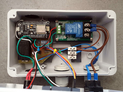
    I wanted to automate an irrigation pump, to be able to turn it on and off remotely and set a power-on time limit. I looked for a ready-made solution and I found some products. But none fit my needs. There are mains powered ESP8266 boards with one or more relays, but those relays are common 10A type. After some searching on AliExpress, I found an ESP8266 module with 30A relay, but this one was missing a mains adapter and required DC low voltage supply. This one could have been my choice. After all I only had to get a power supply.

    Later, I decided to add a small display to my device so, I ended up making my own PCB. A NodeMcu board is the controller of this device. I added a 30A relay module and used a Hi-Link PCB power supply module to deliver required 5 V. The display is a 4-digit 7-segment TM1637 module which came with another challenge. It is a 5 V device that needs to be controlled by a 3.3 V MCU. I added a level shifter module and designed a PCB to fit all of them (except relay module which has its own PCB).

    Electronics for the MQTT switch mounted in a plastic box
    Electronics for the MQTT switch mounted in a plastic box

    Read more

    Značky: #ESP8266, #3D-Print, #Elektro, #MQTT, #Electronics

    • chevron_right

      A proper enclosure for CNC3018 Offline Controller

      pubsub.slavino.sk / onetransistor · Sunday, 2 January, 2022 - 16:48 edit · 1 minute

    I like to have an offline controller for my CNC3018 machine because I want to keep my computer away from the CNC during usage. There is a lot of dust and cut material scraps which shouldn't get into fans and electronics. Speaking of electronics, the offline controller of CNC3018 is just a bare PCB stacked between two nicely machined acrylic plates. There is absolutely no dust protection. Here is issue #1. The next one is that this controller hangs around the CNC. There is no way to attach it to the frame. And the third issue one will encounter when using the offline controller is the loss of computer communication. That is right. As long as the offline controller is plugged in, you cannot connect to CNC via USB. Basically both USB interface and offline controller share the only available serial port of the ATmega328p based mainboard.

    I decided to fix all these issues. Following is a 3D printable enclosure which can be attached to the side of the frame on existing screws. And regarding the serial port issue, there is an optional cable connection mod you can do. Below is the end result.

    AVvXsEiNzsCE9ipnvhxpJ-e5Wf2vXXBgm1SW7VFd8EFYlvUjadIPjFrkzq0EK3OJA_Ctv6dK7EDjKeW8TObkyJqWrh-QHm0HzxqL4X0aFdfzQqOpaYr8Ye22Oa0yTRKNrDpNyqcek1YP35QkNhpaLx-CFZq9nWQcEowD9hTS_wTz5rJeB-EBsyfiziEXoMs6fw=w400-h300
    CNC3018 Offline controler attached to frame side

    Read more

    Značky: #3D-Print, #Elektro, #CNC, #DIY